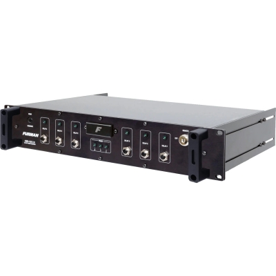
The ASD-120 2.0 AC Sequenced Power Distributor updates the ASD-120, optimized for easier installation and operation. The ASD-120 2.0 is an extremely compact, low cost rackmount power distribution system ideal for touring PA systems, touring musical and theatrical acts, mobile recording facilities, on-location film and video shoots, etc. – any situation where AC power must be distributed to multiple circuits and a hard-wired, built-in system is missing, inadequate or impractical.
The ASD-120 2.0 allows you to power up and its six circuits in a sequenced fashion. The sequence is reversed for power down. The delay interval is user-adjustable via an internal trimpot.
Power sequencing is needed whenever various kinds of equipment must be powered up or down in groups, rather than all simultaneously. In audio systems, sequenced powering is often necessary to allow turn-on transients from low level amplifiers and processors to settle down before any power amps are turned on, because simultaneous powering would result in a loud, annoying, and potentially destructive ‘pop’ reaching the speakers. And in any large system whose components present an inductive load to the AC line (including electric motors, power supplies, and power amplifiers of all kinds), sequenced powering can avoid excessive inrush currents that cause circuit breakers to trip even though the steady-state currents are not excessive.
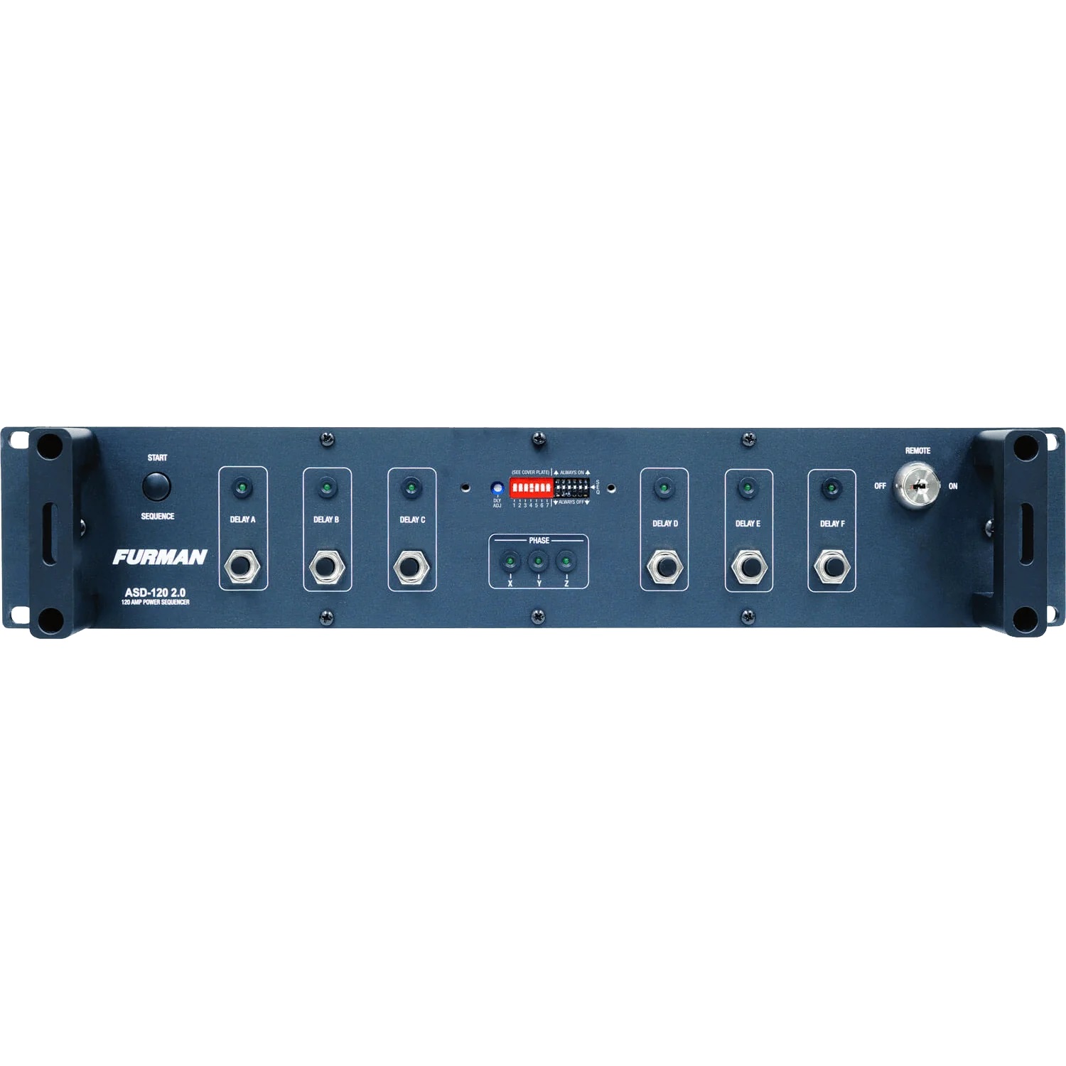
The ASD-120 2.0’s front panel provides a three-position switch for each circuit that allows each circuit to be part of the power up/down sequence, or to remain on or off apart from the sequence. An LED that indicates when either the power-up or power-down sequence is in progress. The sequence can be initiated with either momentary or maintained switches, locally or remotely. A duplex outlet is provided for each delay step. A locking switch with a removable key is provided for maximum security.
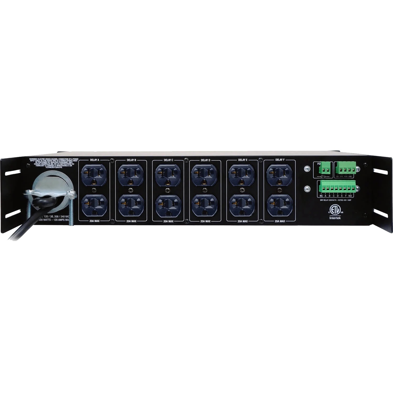
Since the sequence control signals are also available on the rear panel, one or more ASD-120 2.0s may be installed in remote locations and operated via low-voltage control wiring. The sequence control signals can also drive PowerPorts, MiniPorts, PS-PRO and PS-8-R Power Sequencers, or any other circuits that need to know when their particular time delay has elapsed. Using one or more ASD-120’s can provide the capability of controlling power and power sequencing for an entire system.
The ASD-120 2.0 can handle up to 120 amps of incoming power, distributing it to six 20 amp, 120V circuits. Each circuit has a front panel status indicator that lights up when it is turned on, and a 20 amp duplex outlet on the rear panel.
The ASD-120 2.0’s design incorporates four oversized busses, allowing wiring for 120V or 240V single phase, or 208V three phase power. A strain relief clamp is provided that can accommodate a cable or wire bundle up to 1.5 inches in diameter. Cable termination is a simple process of breaking out and stripping the individual conductors and connecting them with set screws, and then tightening the strain relief clamp. Complete instructions accompanying the unit guide the user through the process of selecting and terminating the supply cable.
Technical Specifications
General
Family
Contractor Series
Line Voltage
120 Volts
AC Input
AC Input Voltage
240V single phase or 208V three phase
AC Input Current
120 amps maximum
AC Voltage Input Range
90-139VAC, 50/60Hz
Output
Output
Six 120V 20A circuits
Maximum AC Current Rating
Six 120V 20A circuits for 120A total
Cable Clamp
145R – 1 1/2 inch NM Clamp Type – Wire Size: 2 to 6 AWG
AC Output Receptacles
Rear Panel Outlets
6 duplex NEMA 5-20R sequenced
Front Panel
6 thermal circuit breakers, one per duplex pair
Operating Temperature and Humidity
5 to 40°C (40 to 105°F), <90% Relative Humidity
User Interface (Front Panel)
Key-switch
Front panel, 3 position (On/Off/Remote)
Keys
Included, 1 pair
Push Button Switch
Front panel
Circuit Breakers
Front panel, push-button; 6, 20A Thermal Breakers
Output Circuit Status
Front panel indicators – one per output
Configuration Switches
Front panel, hidden by security cover
Delay Switches
3 maximum delay switches – 1, 2, and 4 minute
Switching Modes
Force Off NO/NC, 12V mode On/Off, GND mode On/Off
Mode Selection
Momentary/Maintained mode selection
Fine Delay Adjustment
Potentiometer hidden by security cover
Programmable Delay
7 minutes delay per step, 35 minutes total delay time
Control/Status/Triggering (Rear Panel)
Remote Terminal
Phoenix-style 4 Pin Connector with Screw Terminals; +12V @ 250mA, STAT, REM, GND (Class 2 wiring)
Delay Outputs
Phoenix-style 8-Pin Connector with Screw Terminals, 6 relay contacts with NO and NC common connections (Class 2 wiring)
Power Consumption
Standby
5 Watts
Sequenced ON
20 Watts
Other
Certifications
Intertek, FCC, RoHS Compliant
Dimensions
Height 3.5″ (8.9 cm)
Width 19″ (48.3 cm)
Depth 10″ (25.4 cm)
Weight 16 lbs
UPC
654061041184


